Single LED
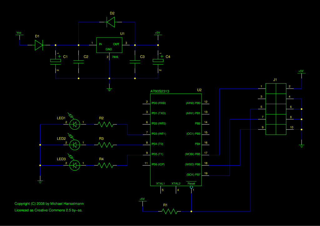
This version is designed for a single LED using less than 40 mA of current, the absolute maximum per I/O pin for the ATtiny2313. Series resistors for the LED must be adjusted depending on the LED used.
| C1, C4 | 10µF |
| C2 | 330nF |
| C3 | 100nF |
| D1, D2 | 1N4001 |
| U1 | LM78L05 |
| U2 | ATtiny2313 |
| J1 | ISP connector |
| LED1 | Red LED |
| LED2 | Green LED |
| LED3 | Blue LED |
| R1 | 10kΩ |
| R2 | 130Ω (~2.4V at LED1) |
| R3, R4 | 100Ω (~3V at LED2..3) |
Schema download: image or source file for gschem
Multiple LEDs
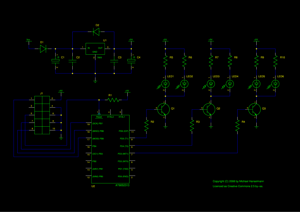
This version uses transistors to drive higher currents than the absolute maximum 40 mA per I/O pin. The type of transistor depends on the current to be driven (the BC337 used below is good for up to 400 mA). More LEDs can easily be added. Series resistors for the LEDs must be adjusted depending on the LEDs used.
| C1, C4 | 10µF |
| C2 | 330nF |
| C3 | 100nF |
| D1, D2 | 1N4001 |
| U1 | LM78L05 |
| U2 | ATtiny2313 |
| J1 | ISP connector |
| LED1, LED2 | Red LED |
| LED3, LED4 | Green LED |
| LED5, LED6 | Blue LED |
| R1 | 10kΩ |
| R2, R3, R4 | 10kΩ |
| R5, R6 | 130Ω (~2.4V at LED1..2) |
| R7, R8, R9, R10 | 100Ω (~3V at LED1..4) |
| Q1, Q2, Q3 | BC337 or 2SD467 |
Schema download: image or source file for gschem
Multiple LEDs with colour selection

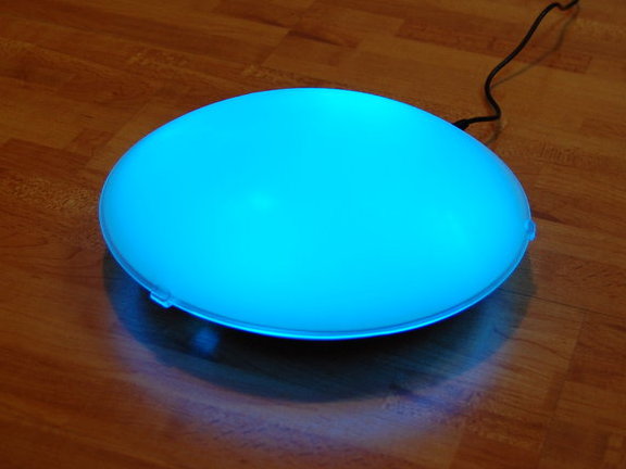
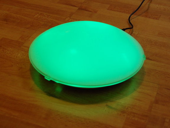
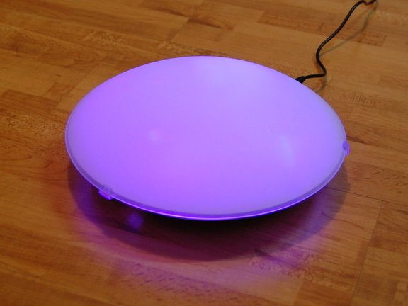
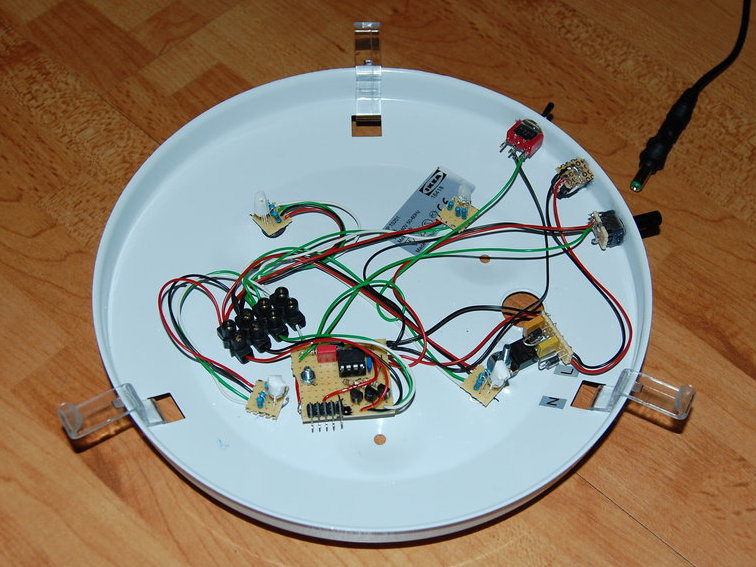
A while ago, I ordered cheap RGB LEDs via an auction platform. I wanted to make use of them and designed this lamp. It’s based on an Ikea lamp called “Lock”. The version pictured has four LEDs installed, but the used transistors could drive up to about twelve of them.
This circuit uses all pins of an ATtiny45 µC, except for the reset pin. The user can change between automatic and manual mode using a switch. In automatic mode, the lamp changes colours automatically and speed can be changed using a potentiometer. In manual mode, the colour is selected using the potentiometer.
| C1, C4 | 10µF |
| C2 | 330nF |
| C3 | 100nF |
| C4 | 10nF |
| D1, D2 | 1N4001 |
| U1 | LM7805 |
| U2 | ATtiny25/45/85 |
| J1 | ISP connector |
| LED1..2 | Red LED |
| LED3..4 | Green LED |
| LED5..6 | Blue LED |
| R1 | 1kΩ |
| R2 | 10kΩ |
| R3 | 10kΩ potentiometer |
| R4..6 | 560Ω |
| R7..8 | 130Ω (~2.4V at LED1..2) |
| R9..12 | 100Ω (~3V at LED3..6) |
| Q1..3 | BC327 |
Download image or source file for gschem, Makefile and C source code.
Licence
The schematics and source code are released under the Creative Commons Attribution-Share Alike 2.5 licence.